![94682b08-af4e-42f2-b868-af7439511c70.jpg]](https://support.growdata.com.au/hs-fs/hubfs/94682b08-af4e-42f2-b868-af7439511c70.jpg?height=50&name=94682b08-af4e-42f2-b868-af7439511c70.jpg)
Stage 1: Removing the Existing Data Logger – These instructions are for reference only
Step 1.1: Power Down the Existing System
- Ensure the current system is powered down before starting the removal process to avoid any electrical issues.
- Unplug the data logger and any connected sensors from the power supply.
Step 1.2: Open the Enclosure and Remove the Data Logger
- To access the data logger, open the enclosure drawer by turning the knob on the bottom side of the enclosure.

- Press on the tab using a screwdriver on the side of the enclosure.
- Slide the box up and remove it carefully.
- Unscrew the base bracket of the old data logger box to free it from its mounting position.
Stage 2: Addressing the Sensors
SDI-12 Sensor Addressing Procedure
The sensors will need to be tested and configured through the following steps. This process allows each sensor to be assigned a specific address on the SDI12 weather sensor data bus, ensuring the data goes to the correct location.
Pre-requisites
- Hardware:

- Jack to wire adapter (if needed)

- SDI-12 sensor to reprogram

- Software:
- SDI-12 Commander Lite (Download from: SDI-12 Commander Setup)
- Data logger driver (Download here)
To download the data logger driver, you will need to click the link above; once downloaded click 'open file'; once opened, select 'extract all' at the top; another window will appear, click 'extract'; double click on the 'CP210xCXPInstaller' file name to open and follow the prompts.
Example video below:
Procedure:
- Prepare the Setup:
- Do not connect the USB to your computer yet.
- Connect the SDI-12 sensor that you are testing to the converter or audio jack.

- Install the SDI-12 Commander Lite software on your computer if not already done. Install driver.
- Connect the TBS03 device to your computer via USB.
- Right-click the Windows start icon and open Device Manager.

- Alternatively, you can type ‘Device Manager” in the search bar.
- Find the "Ports (COM & LPT)" category and expand it.

- Locate "CP210x to Uart Bridge" and note down the COM port number in brackets. This will be needed later.
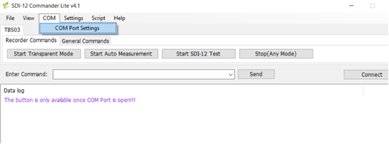
- Open the SDI-12 Lite Commander software and go to "COM port settings."
- Select the previously noted COM port number in the dropdown menu.
- Click "Refresh COMs" if you don’t see the port number and then click OK.
- Click "Connect" to establish a connection with the SDI-12 sensor.
- To test, enter the command “?!” and press "Send"
- The sensor’s current address will be displayed in red.
- If no response is received, send the “?!” command again.

7. Change the Sensor Address:
7.1 To change the sensor address, enter “xAy!” (where X is the current address and Y is the desired address). For example, change address from 0 to 4 by entering “0A4!”. 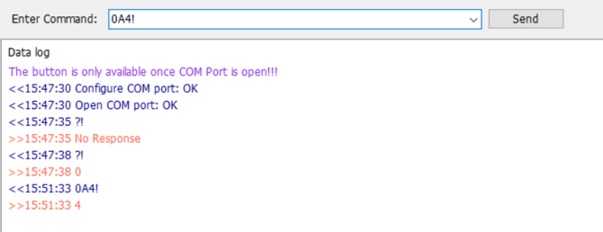
Finally, type “?!” and press send again to check if the sensor returns “4” to confirm the change.
Sensor addressing:
|
Sensor address |
Sensor |
Data output |
|
1 |
SQ-421SS PAR sensor (if present) |
PAR (µmol/m2/s) |
|
2 |
SP-421SS PYR sensor (if present) |
PYR (watts/m2) |
|
3 |
Atmos 14/ Decagon VP-4 |
Vapour Pressure (kPa) Ambient temperature (DegC) Relative Humidity (%) Atmospheric Pressure (kPa) |
|
4 |
Soil sensor Meter GS3 |
Dielectric constant (εa) Soil temperature at probe (degC) Electrical conductivity (µS/cm) |
|
5 |
Soil sensor Meter GS3 |
As above |
|
6 |
Soil sensor Meter GS3 |
As above |
|
7 |
InformAg analog to SDI-12 smart board |
Wind speed (km/h) Wind gust speed (km/h) Wind direction (deg) Rain last 15min (mm) PAR PYR Other additional analog sensors plugged in (limit of 6 total) |
|
8 |
Free |
|
|
|
|
|
VPD and ET0 are calculated values.
- Please confirm that each sensor has successfully been set to its new address by following the instructions from section 7.2.
Stage 3: Installing the Data Logger, Solar Panel, and Antenna
Now that the sensors are addressed and prepared, you can proceed with installing the core components of the system.
Packing list
- SDI-12 Data logger
- Junction cable
- Solar panel with bracket
- Pole screw clamps
- LTE wideband antenna
- Screw pack
- Tube clamp (included in the pack)
Required tools
- Drill and 3 mm drill bit for metal
- 13mm deep socket or 13mm spanner
- Wire/cable stripper
- Cable cutters
- Silicon
- 7mm socket
- 16 mm spanner
- 3 mm and 6 mm Allen key
- Screwdriver set - flat and phillips
Step 3.1: Install the Solar Panel
- Choose the Installation Location:
- Install the solar panels facing north in a location that receives maximum sunlight throughout the day without shade or obstructions.

2. Add cable to the solar panel – remove the panel cover with a small flat blade screwdriver. Take your cable and remove the outer sheath (approx. 100mm) and then remove cable insulation (approx. 20mm) insert cable through cable glands (right side red/positive, left side black/negative. Remove terminal screw and wrap exposed cable around screw. Tighten screw and give the cable a pull to make sure it is tight. Apply silicone to gland holes to prevent any water and bugs entering.
3. Adjust the solar panel bracket to the desired angle and tighten with 6mm allen key and 13mm spanner/socket. Install solar clamp and ends of bracket. (video demonstrating above instructions)
4. Mount the solar panel bracket, inset the u bolts into the bracket, place onto pole and attach bracket clamps, washers, nuts and tighten with 13mm deep socket or spanner. Install solar panel to bracket, align clamp to middle of solar panel and tighten with 6mm allen key. Attach cable to pole with zip ties or run cable through the inside of the pole. Place cable in conduit to avoid any potential damage if necessary. (video demonstrating above instructions)
Step 3.2: Install the Data Logger
- Position the Data Logger:

Open the side lids of the box and insert one of the bolts. Secure one side of the bracket first and then work on the other side. 
Feed one of the bolts through and hold it in place with an Allen key. Add the bracket on the backside of the box and secure it loosely with a washer and a nylock nut. 

Then feed in the second bolt, hold it in place, and secure it with a washer and a nylock nut. Centre the bracket and hand-tighten the bolts with an allen key and a spanner. 

Make sure the bracket is centred before tightening the bolts into place. Do not over-tighten the screws, because it could damage the enclosure. 
Thread the tube clamp through the metal bar and secure the box to the pole
Step 3.3: Install the Antenna
- Position the Antenna:
- Install the antenna in an elevated position to maximize signal reception.
- Use the mounting hardware provided to fasten the antenna securely. Remove the plastic cover and install the mounting bracket to raise the antenna to a high position on the post with 2x self-drilling screws. Sometimes it is advisable to pre-drill the post to avoid slipping and injury during installation. Mark one screw hole on the post, pre-drill, and install the bracket with a self-drilling screw, then pre-drill the second hole and install the second screw.


Feed the cable and connector through the bracket and remove the slotted nut from the antenna. Feed the cable through the slotted nut and secure the antenna to the bracket with the slotted nut. Do not over-tighten the nut, because it could damage the antenna.
3. Connect the Antenna:- Connect the antenna cable to the data logger, ensuring a secure connection. Tighten the connectors but avoid over-tightening to prevent damage.

- If you have excess antenna cable, wind it up in a figure-eight motion and secure it to the post with a cable tie.

Step 3.4: Connections
Remove the front lid of the data logger to access the cables. Please be careful when removing the lid as the batteries may have become dislodged and may fall out of the box. If this has occurred, please reinstall batteries and make sure there is a small gap (approx. 2mm) between the batteries and the right side if the box internals.
Power up the Data Logger:
- Feed the solar panel cable through the cable gland and connect into the solar terminal block (bottom left side terminal)
- Connect the cables making sure the black cable goes to the left and the red cable connects to the right.


- Remove the yellow protective caps from the batteries and connect the cables. Black cable to the black negative pole of the battery and red cable to the red positive pole of the battery. Connect cables into the battery terminal block (bottom right side terminal) making sure the black cable goes to the left and the red cable connects to the right.


- Turn power switch on.
If, for any reason, the red lights do not come on, please contact our support team at:
+61 7 3184 8165 or support@growdata.com.au
If everything looks as in the above photo, close the lid of the enclosure and tighten the screws hand-tight in a crosswise fashion. Start with the top left corner and tighten the screw until you feel some resistance. Do not overtighten the lid screws. Then move to the bottom right screw, followed by the top right screw, and finally the bottom left screw. Repeat the process until the lid is securely tightened.
Once you have completed the installation, send our support team an email or give us a call and we will check that the unit is communicating properly.